FMOD Studio User Manual 2.02
- Welcome to FMOD Studio
- FMOD Studio Concepts
- Organizing the Project
- Authoring Events
- Working with Instruments
- Managing Assets
- Parameters
- Getting Events into Your Game
- Mixing
- The Sandbox
- Editing During Live Update
- Profiling
- Dialogue and Localization
- Using Source Control
- Supporting Downloadable and User-generated Content
- Advanced Topics
- Quick Start Tutorial
- Effect Reference
- Event Macros Drawer Reference
- Instrument Reference
- Keyboard Shortcut Reference
- Modulator Reference
- Parameters Reference
- Plug-in Reference
- Scripting
- Scripting API Reference
- Troubleshooting
- Glossary
- Appendix: Celeste Getting Started Guide
- Appendix: Reaper Integration
18. Effect Reference
An effect is a modular unit that can be inserted into the signal chain of a track or bus, and which can perform real-time signal processing, routing, or analysis.
Effects are displayed as panels in the deck when viewing the signal chain to which they have been added. The order of effects in the signal chain determines the order in which they are applied to the signal.
Most effects have properties that are automatable and modulatable, meaning that their values can be adjusted in real time. This allows an effect property to have different values at different times and in different event instances.
Some effects are instances of preset effects and can be present in multiple different events in the project. All instances of a single preset effect feature the same basic property values, automation, and modulation.
For information on using effects to process signals in your project's buses and tracks, see the Signal Chains section of the Authoring Events chapter.
The following properties and controls are common to many effects.
- Effect Name (Label)

- The name of the effect or preset effect.
- Bypass (Toggle button)

- Any effect can potentially be bypassed, suppressing its normal function for as long as it remains bypassed. A bypassed routing effect does not route a duplicate of the signal at its location to its target destination, and a bypassed creative effect does not alter the signal at its position in the signal chain. Effects that change the channel format of the signal at their position in the signal chain are a partial exception to this; such an effect always alters the channel format of the signal even when it is bypassed, though it will not alter the signal in any other way that it normally would.
- Bypassing does not affect in-game behavior; it only affects behavior when auditioning in FMOD Studio and when using live update to connect FMOD Studio to your game.
- Preset Effect Icon (Button)

- This icon is present if the effect is based on a preset effect, and flashes whenever the preset effect is being changed.
- Clicking on the preset effect icon opens the preset effect in the presets window.
- Platform Exclusion Icon (Button)

- This icon is present if the effect is excluded from at least one of your project's target platforms. If it is excluded from the current platform, the icon is blue and the effect is dimmed; if the effect is not excluded from the current platform, the icon is gray.
18.1 3-EQ

The FMOD 3-EQ is a three-band equalizer: It allows you to define three frequency bands, "low," "mid," and "high," and to adjust the gain of each band. This allows you to emphasize or de-emphasize specific parts of a signal.
The 3-EQ effect is built on the FMOD Engine's Three EQ effect.
Performance: Low overhead.
- Low (Dial)

- This is the gain to be applied to the low band.
- Range: -oo dB to +10 dB. Default value: 0 dB.
Automatable and Modulatable. - Mid (Dial)

- This is the gain to be applied to the mid band.
- Range: -oo dB to +10 dB. Default value: 0 dB.
Automatable and Modulatable. - High (Dial)

- This is the gain to be applied to the high band.
- Range: -oo dB to +10 dB. Default value: 0 dB.
Automatable and Modulatable. - X-Low (Dial)

- This property's value defines the upper end of the low band and the lower end of the mid band. The lower end of the low band has no lower limit.
- Range: 10 Hz to 22 kHz. Default value: 400 Hz.
Automatable and Modulatable. - X-High (Dial)

- This property's value defines the upper end of the mid band and the lower end of the high band. The upper end of the high band has no upper limit.
- Range: 10 Hz to 22 kHz. Default value: 4 kHz.
Automatable and Modulatable. - X-Slope (Radio buttons)

- The boundary between bands is not sharply delimited. The upper end of the low band is crossfaded with the lower end of the mid band, and the upper end of the mid band is crossfaded with the lower end of the high band, to prevent abrupt and obvious steps in volume when a sound gradually changes frequency.
- This property defines the slope of the curves used in the crossfade, 12 dB being the shallowest and gentlest curve, and 48 dB being the steepest. The default slope is 24 dB.

A graph showing the curves used for each x-slope property value when the low, mid, and high properties are set to 0 dB, and x-low and x-high are set to below 100 Hz and above 10,000 Hz respectively.
18.2 Channel Mix


This effect allows you to manipulate the individual speaker channels of a signal, routing any input speaker channel into any output speaker channel. Among other things, this allows the channel mix effect to be used as a low-cost multi-layer audio system, in which multiple input speaker channels are grouped (i.e.: routed and mixed) into a single output speaker channel. This is especially useful for streaming audio, as it allows a single streaming asset to take the place of multiple streaming assets, and for a single audio track and instrument to take the place of multiple audio tracks and instruments.
The number of channel gain sliders that appears depends on the speaker channel format of the channel mix effect's input signal.
The channel mix effect is built on the FMOD Engine's channel mix effect.
Performance: Low overhead.
- Grouping (Drop-down menu)

- This property sets the output channel format of the effect, and thus defines what speaker channels the input speaker channels can potentially be grouped (i.e.: routed and mixed) into. If set to "none," the effect output speaker channel format is the same as its input speaker channel format, and each input channel outputs to the equivalent output channel. If set to anything other than "none" or "mono," output channel drop-down menus appear beneath each channel gain slider.
- Default value: None.
- Channel gain sliders (Sliders)

- These sliders, labelled "Ch. 0," "Ch. 1," and so on, correspond to the speaker channels of the effect's input signal, and allow you to duck or boost their volumes. The number of sliders on the effect depends on the number of speaker channels in that channel format.
- The sliders are presented in standard channel order (i.e.: L, R, C, LFE, LS, RS, LSR, RSR, TFL, TFR, TBL, TBR), regardless of which metering channel order is selected in the audio tab of FMOD Studio's preferences dialog.
- Range: -oo dB to +10 dB. Default value: 0 dB.
Automatable and Modulatable. - Output channel drop-down menus (Drop-down menus)

- These menus appear beneath each channel gain slider if the grouping drop-down menu is set to anything other than "mono" or "none." Each such menu lists all the speaker channels in the output speaker channel format specified by the grouping drop-down menu. Setting an output channel drop-down menu to a speaker channel causes the input speaker channel to be grouped (i.e.: routed and mixed) into that output speaker channel. For example, the "Ch. 1" slider usually represents the front right speaker channel. If you set the drop-down menu below that slider to "C," the channel mix effect routes the front right speaker channel's signal to the center channel.
18.3 Chorus

The chorus effect generates interference of the source signal by mixing it with a three delayed copies of that signal, and modulating the delay offset of those copies over time. The result sounds choral, as if multiple sources were producing the same sound at approximately the same time.
The output of the chorus effect is balanced such that its output is not louder than its input.
The effect works best on longer sounds that are sustained for some time.
The chorus effect is built on the FMOD Engine's chorus effect.
Performance: Medium overhead.
- Rate (Dial)

- The frequency with which the delay offset of the delayed copies oscillates.
- Range: 0 Hz to 20 Hz. Default value: 0.8 Hz.
Automatable and Modulatable.

- Depth (Dial)

- The maximum delay offset applied to the delayed copies, expressed as a percentage. 0% represents 0 ms, 100% represents 100 ms. Values between those extremes follow the formula (delay in ms) = 100 × (property value)2, such that a value of 50% results in a delay of 25 ms.
- Range: 0 % to 100%. Default value: 3%.
Automatable and Modulatable. - Mix (Dial)

- The wet/dry mix of this effect to be applied to the signal. The loudness of the mixed signal is automatically balanced to ensure the loudness of the output signal is consistent with that of the input signal.
- Range: 0% to 100%. Default value: 100%.
Automatable and Modulatable.
18.4 Compressor

The compressor reduces the volume of sounds above a certain threshold, reducing the signal's dynamic range.
A compressor may be controlled by either its input signal or by a signal from a sidechain effect in the same event or mixer as that compressor effect.
When the peak loudness of the control signal exceeds the threshold property, the volume of the processed signal is ducked according to its ratio property. However, this ducking does not happen instantaneously; whenever the peak loudness increases to a new value above the threshold, the adjustment is ramped up over a period of time based on the attack property; and whenever the peak loudness drops below the threshold, the adjustment is ramped down over a period of time based on the release property.
The compressor effect is built on the FMOD Engine's compressor effect.
Performance: Medium overhead.
- Threshold (Dial)

- This property defines the loudness above which the signal is ducked by the compressor effect. Signals quieter than this value are never ducked, and the compressor cannot duck a signal below this value.
- Range: -60 dB to 0 dB. Default value: 0 dB.
Automatable and Modulatable. - Ratio (Dial)

- This property defines the ratio of the number of decibels the input signal's volume is above the threshold to the number of decibels above the threshold the compressor should reduce it to. A ratio property of 2.5:1 therefore means that for every 2.5 dB the signal is above the threshold, that signal is attenuated by 1.5 dB.
- For example, suppose the threshold is -12 dB and the signal's loudness is -6 dB. If the ratio is 2:1, the compressor attenuates the signal by -3 dB; if the ratio is 3:1, the compressor attenuates the signal by -4 dB; and if the ratio is 1:1, the compressor does not attenuate the signal.
- Range: 1.0:1 to 50.0:1. Default value: 2.5:1.
Automatable and Modulatable. - Attack (Dial)

- This property defines the amount of time over which the signal's volume may be ramped down when peak loudness increases to a new value above the threshold.
- Range: 0.1 ms to 500 ms. Default value: 20 ms.
Automatable and Modulatable. - Release (Dial)

- This property defines the amount of time over which the signal's volume may be ramped up when the signal's peak loudness decreases from a value above the threshold.
- Range: 10 ms to 5 sec. Default value: 200 ms.
Automatable and Modulatable. - Gain (Dial)

- This property represents a gain adjustment that's applied to the signal before compression.
- Range: -30 dB to +30 dB. Default value: 0 dB.
Automatable and Modulatable. - Channels (Toggle button)

- This property determines whether the speaker channels of the signal are processed individually or as a group. If disabled, each speaker channel is processed individually, and so is only affected by compression if that specific speaker channel (or the corresponding speaker channel of the control signal) exceeds the threshold; if enabled, all speaker channels are subject to equal compression whenever compression is applied, as if they had been down-mixed to mono speaker format.
- Sidechain (Dropdown menu)

- This menu determines the sidechain (if any) linked to the compressor effect. If set to "No Inputs," the compressor effect is controlled by its input signal; whereas if it is set to a sidechain effect, the compressor effect is instead controlled by the signal from that sidechain effect.
18.5 Convolution Reverb

The convolution reverb effect uses an impulse response to simulate the reverberation characteristics of a real or fictional location and applies those characteristics to the signal.
The convolution reverb effect allows more accurate reproduction of real-world locations' reverberation characteristics than the reverb effect. However, unlike the reverb effect, it does not support adjusting or morphing reverb characteristics in real time. It is possible to work around this limitation by using multiple different convolution reverb effects on different tracks or buses and crossfading between them, but using multiple convolution reverb effect instances incurs a commensurate increase in resource cost.
The convolution reverb effect is built on the FMOD Engine's convolution reverb effect.
Performance: High overhead. Shorter impulse responses require less CPU time to process, while longer impulse responses require more.
- Impulse Response (Graphic)

- The impulse response used by the effect. To add or change the impulse response used by a convolution reverb effect, drag an appropriate file from Finder or Explorer onto this widget. Suitable impulse response files must be in 16 bit PCM format, and must have a sample rate equal to your game's output rate. For more information on impulse response files, see the Creation of an impulse response for use with the convolution reverb effect section of the FMOD Engine User Manual. The spaker channel format of the impulse response file determines the speaker channel format of the effect's output.
- The section of the graphic displayed with a medium gray background represents the parts of the waveform that are louder than -80 dB. Sections of the waveform quieter than this threshold are treated as silent for the purposes of impulse response calculation, in order to conserve resources.
- Wet Level (Dial)

- The level of signal processed by this effect to be included in the effect's output.
- Range: -oo dB to +10 dB. Default value: 0 dB.
Automatable and Modulatable. - Dry Level (Dial)

- The level of the unprocessed input signal to be included in the effect's output.
- Range: -oo dB to +10 dB. Default value: -oo dB.
Automatable and Modulatable. - Channels (Toggle Button)

- Determines whether the channels should be linked or unlinked. If linked, the input signal is down-mixed to mono format before being processed by this effect. If unlinked, the input signal is down-mixed or up-mixed to match the channel format of the impulse response before being processed. Unlinked mode is therefore most useful when the channel format of the impulse response matches that of the signal.
- Default value: Linked.
- Meters (Meters)

- Displays the levels of the effect's output. Each displayed meter represents a different speaker channel of the effect's output, and the order in which they are displayed corresponds to the metering channel order set in the "Audio" tab of the preferences dialog. The filled section of each meter represents the root mean square (RMS) level of the signal in that speaker channel averaged over 300ms, and the bar that appears above each filled meter section represents the peak level of the signal in that speaker channel. The speaker channel format of the effect's output is that of the impulse response file.
18.6 Delay

The delay effect stores a copy of the signal, and mixes it back into the signal after a specific amount of time. This can be used to simulate a reflection of a sound that arrives some time after the initial sound is heard. While a delay effect is not as detailed and subtle as a reverb or convolution reverb effect, it is a cheap and effective way to simulate the early, harsh reflections of an echoed sound.
The delay effect is built on the FMOD Engine's echo effect.
Performance: Medium overhead.
- Delay (Dial)

- The amount of time delay applied to the copy of the signal.
- Range: 1 ms to 5 sec. Default value: 500 ms.
Automatable and Modulatable. - Feedback (Dial)

- The amount of the signal to be fed back into the buffer after the initial delay. This determines how much the second and subsequent echoes fade with each subsequent iteration.
- Range: 0% to 100%. Default value: 50%.
Automatable and Modulatable. - Wet Level (Dial)

- The level of the delayed signal to be mixed into the effect's output. This determines how loud all the echoes are.
- Range: -oo dB to +10 dB. Default value: 0 dB.
Automatable and Modulatable. - Dry Level (Dial)

- The level of the non-delayed original signal to be mixed into the effect's output. If this is set to a low value, the original signal may be quieter than its echoes.
- Range: -oo dB to +10 dB. Default value: 0 dB.
Automatable and Modulatable.
18.7 Distortion

The distortion effect alters the shape of a signal to make it sound noisier. This can be used to simulate poor-quality or degraded recordings and signals.
The effect is achieved by amplifying then clipping the signal at a level determined by the effect's level property.
The distortion effect is built on the FMOD Engine's distortion effect.
Performance: Low overhead.
- Level (Dial)

- The degree of distortion to be applied to the signal.
- Range: 0% to 100%. Default value: 50%.
Automatable and Modulatable.
18.8 Flanger

The flanger effect overlays the dry signal with a single delayed copy of that signal, and modulates the offset of the delay over time. The result is an oscillating phase shift, which is audible as a repetitive whooshing, sweeping effect. In addition, the levels of both signals are adjusted downward to ensure the loudness of the output signal is not significantly different to that of the input signal.
The flanger effect is most commonly used in music, though it is sometimes also used in ambiances to create an otherworldly atmosphere.
The flanger effect is built on the FMOD Engine's flange effect.
Performance: Medium overhead.
- Rate (Dial)

- The frequency with which the delay offset oscillates.
- Range: 0 Hz to 20 Hz. Default value: 0.1 Hz.
Automatable and Modulatable. - Depth (Dial)

- The maximum delay offset.
- Range: 0.01 ms to 1 ms. Default value: 1 ms.
Automatable and Modulatable. - Mix (Dial)

- The mix of the dry signal and the overlaid copy.
- Range: 0% (Dry) to 100% (Vibrato). Default value: 50%.
Automatable and Modulatable.
18.9 Gain

The gain effect adjusts the volume of the signal.
The gain effect is equivalent to the FMOD Engine's fader effect.
Performance: Low overhead.
- Gain (Dial)

- The volume adjustment to be applied to the signal.
- Range: -oo dB to +10 dB. Default value: 0 dB.
Automatable and Modulatable.
18.10 Limiter

The limiter effect allows you to prevent the signal from exceeding a certain amplitude. Whenever the signal would exceed that amplitude, the limiter scales the signal to stay below it. When the signal would no longer exceed that amplitude, the signal is ramped back up to its original scale.
Limiter effects can be used to control dynamics and avoid signal clipping.
The limiter effect is built on the FMOD Engine's limiter effect.
Performance: Low overhead.
- Input (Dial)

- The amount of gain to be applied to the input signal before any other processing by this effect.
- Range: 0 dB to 12 dB. Default value: 0 dB.
Automatable and Modulatable. - Ceiling (Dial)

- The maximum amplitude that the signal may reach without being scaled.
- Range: -12 dB to 0 dB. Default value: 0 dB.
Automatable and Modulatable. - Release (Dial)

- The period over which the signal is ramped back to its original scale after ceasing to exceed the ceiling.
- Range: 1 ms to 1 sec. Default value: 10 ms.
Automatable and Modulatable. - Channels (Toggle button)

- This property determines whether the effect should operate in linked mode or unlinked mode. In linked mode, the channels are summed together and treated as a mono signal for the purposes of this effect; in unlinked mode, each channel is processed and limited separately.
- Default value: Linked.
18.11 Multiband EQ

The multiband EQ effect is a five-band parametric equalizer that allows you to attenuate or accentuate specific frequencies of a signal. Each of its five bands (A, B, C, D, and E) can be assigned a different type of filter.
The multiband EQ effect is built on the FMOD Engine's multiband equalizer effect.
Performance: Low overhead to medium overhead. Each band of a multiband EQ effect is a separate filter that incurs its own CPU cost. The more bands are enabled (i.e.: set to a filter type other than "Off"), the higher the effect's total CPU cost.
- Filter Graphic (Mouse-editable graphic)

- This graphical display allows you to edit the properties of the displayed band's filter by clicking and dragging the letter-in-a-circle symbol. Dragging the icon horizontally alters the filter's frequency property, and dragging it vertically alters the filter's Q or gain property. These properties are described in more detail below.
- The scale on the left side represents the gain and is used by the red graph line, and the scale on the right side represents the phase, and is used by the gray graph line.
- Band Selection (Radio buttons with inset dropdown menus)

- These five buttons, labeled A, B, C, D, and E, determine which band of the effect is displayed in the filter graphic and has its properties displayed on the right side of the effect.
- Filter type (Dropdown menus)

- These five dropdown menus, located on the band selection radio buttons, define the type of filter to be used by their associated bands. Each can be set to one of the following filter types:
-
- LP 12 dB. A resonant filter that attenuates frequencies above a specified cutoff frequency at a rate of 12 dB per octave. In this filter type, the frequency property represents the frequency to be used as the cutoff frequency, and the Q property controls the resonance of the effect, which is a linear gain to be applied at the cutoff frequency.
-
- LP 24 dB. A resonant filter that attenuates frequencies above a specified cutoff frequency at a rate of 24 dB per octave. In this filter type, the frequency property represents the frequency to be used as the cutoff frequency, and the Q property controls the resonance of the effect, which is a linear gain to be applied at the cutoff frequency.
-
- LP 48 dB. A resonant filter that attenuates frequencies above a specified cutoff frequency at a rate of 48 dB per octave. In this filter type, the frequency property represents the frequency to be used as the cutoff frequency, and the Q property controls the resonance of the effect, which is a linear gain to be applied at the cutoff frequency.
-
- HP 12 dB. A resonant filter that attenuates frequencies below a specified cutoff frequency at a rate of 12 dB per octave. In this filter type, the frequency property represents the frequency to be used as the cutoff frequency, and the Q property controls the resonance of the effect, which is a linear gain to be applied at the cutoff frequency.
-
- HP 24 dB. A resonant filter that attenuates frequencies below a specified cutoff frequency at a rate of 24 dB per octave. In this filter type, the frequency property represents the frequency to be used as the cutoff frequency, and the Q property controls the resonance of the effect, which is a linear gain to be applied at the cutoff frequency.
-
- HP 48 dB. A resonant filter that attenuates frequencies below a specified cutoff frequency at a rate of 48 dB per octave. In this filter type, the frequency property represents the frequency to be used as the cutoff frequency, and the Q property controls the resonance of the effect, which is a linear gain to be applied at the cutoff frequency.
-
- Lowshelf. A filter that boosts or attenuates lower frequencies. In this filter type, the gain property represents the maximum adjustment to be applied to the signal. The frequency property represents the frequency at which exactly half the boost or attenuation is to be applied.
-
- Highshelf. A filter that boosts or attenuates higher frequencies. In this filter type, the gain property represents the maximum adjustment to be applied to the signal. The frequency property represents the frequency at which exactly half the boost or attenuation is to be applied.
-
- Peaking. A filter that boosts or attenuates the frequencies surrounding and including a specified frequency. In this filter type, the gain property represents the maximum adjustment to be applied to the signal, and the frequency property represents the frequency to be adjusted. The Q property represents the bandwidth of the effect, which is to say, how broad or narrow the affected frequency range is.
-
- Bandpass. A filter that attenuates frequencies that differ from a specified frequency. In this filter mode, frequency controls the specified frequency and Q controls how rapidly attenuation increases as the frequency moves away from the specified frequency.
-
- Notch. A filter that attenuates a specified frequency and nearby frequencies. In this filter made, frequency controls the specified frequency and Q controls how rapidly attenuation decreases as the frequency moves away from the specified frequency.
-
- Allpass. A filter that modifies the phase response at the specified frequency without otherwise changing the signal. This filter is useful for reducing (or increasing) the audible phasing that can occur when the modified signal is mixed with other signals.
-
- Off. A lack of filter.
- Freq. (A) (Number box)
 number box.")
- The frequency used by the A band's filter. This property only appears when the A band is displayed in the filter graphic.
- Range: 20 Hz to 22 kHz. Default value: 660 Hz.
Automatable and Modulatable. - Q (A) (Number box)
 number box.")
- The Q value used by the A band's filter. This property only appears when the A band is displayed in the filter graphic. The exact function of the Q value depends on the filter type, as described above.
- Range: 0.1 to 10. Default value: 0.71.
Automatable and Modulatable. - Gain (A) (Dial)
 dial.")
- The frequency used by the A band's filter. This property only appears when the A band is displayed in the filter graphic.
- Range: -30 dB to 30 dB. Default value: 0 dB.
Automatable and Modulatable. - Freq. (B) (Number box)
 number box.")
- The frequency used by the B band's filter. This property only appears when the B band is displayed in the filter graphic.
- Range: 20 Hz to 22 kHz. Default value: 40 Hz.
Automatable and Modulatable. - Q (B) (Number box)
 number box.")
- The Q value used by the B band's filter. This property only appears when the B band is displayed in the filter graphic. The exact function of the Q value depends on the filter type, as described above.
- Range: 0.1 to 10. Default value: 0.71.
Automatable and Modulatable. - Gain (B) (Dial)
 dial.")
- The frequency used by the B band's filter. This property only appears when the B band is displayed in the filter graphic.
- Range: -30 dB to 30 dB. Default value: 0 dB.
Automatable and Modulatable. - Freq. (C) (Number box)
 number box.")
- The frequency used by the C band's filter. This property only appears when the C band is displayed in the filter graphic.
- Range: 20 Hz to 22 kHz. Default value: 11 kHz.
Automatable and Modulatable. - Q (C) (Number box)
 number box.")
- The Q value used by the C band's filter. This property only appears when the C band is displayed in the filter graphic. The exact function of the Q value depends on the filter type, as described above.
- Range: 0.1 to 10. Default value: 0.71.
Automatable and Modulatable. - Gain (C) (Dial)
 dial.")
- The frequency used by the C band's filter. This property only appears when the C band is displayed in the filter graphic.
- Range: -30 dB to 30 dB. Default value: 0 dB.
Automatable and Modulatable. - Freq. (D) (Number box)
 number box.")
- The frequency used by the D band's filter. This property only appears when the D band is displayed in the filter graphic.
- Range: 20 Hz to 22 kHz. Default value: 160 Hz.
Automatable and Modulatable. - Q (D) (Number box)
 number box.")
- The Q value used by the D band's filter. This property only appears when the D band is displayed in the filter graphic. The exact function of the Q value depends on the filter type, as described above.
- Range: 0.1 to 10. Default value: 0.71.
Automatable and Modulatable. - Gain (D) (Dial)
 dial.")
- The frequency used by the D band's filter. This property only appears when the D band is displayed in the filter graphic.
- Range: -30 dB to 30 dB. Default value: 0 dB.
Automatable and Modulatable. - Freq. (E) (Number box)
 number box.")
- The frequency used by the E band's filter. This property only appears when the E band is displayed in the filter graphic.
- Range: 20 Hz to 22 kHz. Default value: 2.7 kHz.
Automatable and Modulatable. - Q (E) (Number box)
 number box.")
- The Q value used by the E band's filter. This property only appears when the E band is displayed in the filter graphic. The exact function of the Q value depends on the filter type, as described above.
- Range: 0.1 to 10. Default value: 0.71.
Automatable and Modulatable. - Gain (E) (Dial)
 dial.")
- The frequency used by the E band's filter. This property only appears when the E band is displayed in the filter graphic.
- Range: -30 dB to 30 dB. Default value: 0 dB.
Automatable and Modulatable.
18.12 Object Spatializer

The object spatializer is a multi channel effect designed to work with 3D platform-specific spatialization technologies such as Windows Sonic, PlayStation VR, and Dolby Atmos. It functions by routing the signal and the event's 3D positional information directly to a hardware device, bypassing the proceeding signal chain. If the platform-specific technology cannot service the object spatializer due to a lack of available hardware resources, the object spatializer will fallback to using a spatializer effect instead. The object spatializer does not output any audio to the mixer, and any effects placed after an object spatializer will not receive any input from it. Because it bypasses the mixer the output of object spatializers cannot be recorded with the profiler.
The object spatializer effect is built on the FMOD Engine's object pan effect.
Performance: Low overhead.
- Distance Attenuation (Radio buttons and roll-off graph)

- This is the roll-off mode used to change the relationship between audio attenuation and distance. The available roll-off modes are:
-
- Linear Squared. Linear Squared roll-off keeps the volume unattenuated below the min distance, then attenuates to silence using a linear squared gradient to silence at the max distance. This gives it a faster roll-off near the min distance, and a slower roll-off nearer to the max distance than linear mode.
-

-
- Linear. Linear roll-off keeps the volume unattenuated below the min distance, then attenuates to silence using a linear gradient to silence at the max distance.
-

-
- Inverse. Inverse roll-off keeps the volume unattenuated below the min distance, then attenuates at a rate using min distance / distance as the gradient until it reaches max distance where it stops attenuating.
-

-
- Inverse Tapered. Inverse tapered is a combination of "inverse" roll-off and "linear squared" roll-off. From min distance onwards "inverse" is used, and then if the gain is lower with "linear squared", it will switch to that to ensure the gain hits silence at the max distance.
-

-
- Off. No distance-based attenuation is applied.
-

- Envelopment (Radio)

- This determines the extent of the event at any distance from the listener.
-
- Auto. Auto mode sets min extent to 0 degrees and sets sound size to twice the object spatializer's min distance property, and is usually sufficient to prevent event instances from suddenly "flipping" from one side of the listener to the other when they pass the listener at close range.
-
- User. User mode allows you to specify the object spatializer's sound size and min extent manually using the "sound size" and "min extent" controls.
-
- Off. Off mode disables the "sound size" and "min extent" controls.
-
Default value: Auto.
- Sound Size (Dial)

- The sound size has an effect on the panner's extent, based on how 'large' the sound is. A very small sound is concentrated more into a point source (a small extent) and a large sound is spread around the speakers more to convey a sense of envelopment (a large extent).
- Range: 0 to 10000. Default value: 0.
Automatable and Modulatable. - Min Extent (Dial)

- The min extent has an effect on the panner's extent, by acting as a clamp against the sound size's effect on it. If a sound size becomes small which can reduce the distribution of pan to a point source, the min extent can set an angle to guarantee that the object spatializer does not distribute the signal below this value.
- Range: 0 deg to 360 deg. Default value: 0 deg.
Automatable and Modulatable. - Distance Override (Drawer)


- Drawer containing the "override" and "min & max distance" controls.
- Override (Radio)

- This can be used to override the event's min and max distance property controls.
-
- On. On disables the event's min and max distance property controls and enables the "min & max distance" slider, allowing you to specify a different min & max distance for the effect.
-
- Off. Off mode disables the Min & Max slider and enables the event's min and max distance property controls.
-
Default value: Off.
- Min & Max Distance (Draggable slider)

- The min and max distance properties are used by spatializing effects in order to calculate attenuation falloff. Additionally, the value of the normalized distance property is calculated using the min and max distance property values. The min and max distance property controls are only interactive if "override" is set to "on".
- Range: 0 to 10000. Default range: [1,20].
Automatable and Modulatable. - Send meters (Send meters)

- These meters indicate the signal strength of each speaker channel of the signal sent to the platform-specific spatialization technology. The number of meters corresponds to the number of channels in the signal's channel format, and their order is determined by the metering channel order setting in the audio tab of the preferences window. Within each meter, the filled colored bar represents the RMS value of the corresponding speaker channel's signal in dB, and the line above it represents the peak value of that speaker channel.
18.13 Panner


The panner effect applies 2D panning to the signal, optionally alters its speaker channel format, and can also be used to mute any of the signal's individual speaker channels. This can be used to give the impression of spatialization even to 2D sounds, or to mask specific speaker channels out of the mix.
Under-the-hood, the panner effect uses the same code as the track output panner, and so can process the signal in the exact same ways. Unlike the track output panner, however, the panner effect can be positioned in the middle of a track's signal chain, and can be made a preset effect or included in an effect chain.
The panner effect is built on the FMOD Engine's pan effect.
Performance: Low overhead.
- Channel format (Dropdown menu)

- The channel format to which the effect up-mixes or down-mixes the signal, and thus the channel format of the effect's output signal. If this is set to "Automatic," the effect's channel format is preserved instead of altered. As all other controls that appear on this effect are specific to particular channel formats, this dropdown menu also determines which other controls appear on this effect in the deck.
- Default value: Automatic.
- Level meters (Level meters)

- These meters indicate the signal strength of each speaker channel of the signal. The number of meters corresponds to the number of channels in the signal's channel format, and their order is determined by the metering channel order setting in the audio tab of the preferences window. Within each meter, the filled colored bar represents the RMS value of the corresponding speaker channel's signal in dB, and the line above it represents the peak value of that speaker channel.
- Pan (Dial)

- The panning to be applied to a stereo signal. This control only appears if the effect's channel format is set to stereo.
- Range: -100 to +100. Default value: 0.
Automatable and Modulatable. - Surround panner (Mouse-editable graphic)


- The panning to be applied to the signal. This control only appears if the effect's channel format has more than two channels.
- If the channel format of the effect's input signal is anything other than stereo, the surround panner lets you pan the signal between all available speakers by clicking and dragging the white dot at its center. This alters the effect's "direction" and "extent" properties.
- If the effect's input signal's channel format is stereo, the surround panner has two possible modes for converting the stereo signal to surround. In "Stereo In: Distributed" mode, the surround panner lets you pan the signal between all available speakers by clicking and dragging the white dot at its center, as above. In "Stereo In: L/R" mode, the white dot represents the left speaker and the red dot represents the right speaker. Moving the empty circle pans the sound (altering the "axis" property), and moving the red or white dots adjusts the stereo width (altering the "width" property). To switch between these two modes, right click on the panner and select your choice of mode from the context menu.
- Direction (Number box)

- The direction in which the signal is panned. This control only appears if the effect's input signal has more than two channels, or if the input signal is stereo, the effect's channel format has more than two channels, and the surround panner is in "Stereo In: Distributed" mode.
- Range: -180 deg to +180 deg. Default value: 0 deg.
Automatable and Modulatable. - Extent (Number box)

- The size of the arc over which sound is distributed in the output speaker circle. This control only appears if the input signal has more than two channels, or if the effect's input signal is stereo, the channel format has more than two channels, and the surround panner is in "Stereo In: Distributed" mode.
- Range: 0 deg to 360 deg. Default value: 360 deg.
Automatable and Modulatable. - Axis (Number box)

- The orientation of the arc over which sound is distributed in the output speaker circle. This control only appears if the input signal is in stereo channel format, the effect's channel format has more than two channels, and the surround panner is in "Stereo In: L / R" mode.
- Range: -180 deg to +180 deg. Default value: 0 deg.
Automatable and Modulatable. - Width (Number box)

- The width of the pan distribution or size of the arc over which sound is distributed in the output speaker circle. This control only appears if the input signal is in stereo channel format, the effect's channel format has more than two channels, and the surround panner is in "Stereo In: L / R" mode.
- Range: -180 deg to +180 deg. Default value: 60 deg.
Automatable and Modulatable.
18.14 Parametric EQ
The Parametric EQ effect is no longer being actively developed and optimized. While it may still be used in FMOD Studio, we recommend instead using a multiband EQ effect and setting it to the peaking filter type.

The FMOD parametric EQ effect is a single-band peaking equalizer filter effect. It allows you to amplify or attenuate a bandwidth surrounding and including a specified frequency. This allows you to emphasize or de-emphasize specific parts of a signal.
The Parametric EQ effect is built on the FMOD Engine's Parametric EQ effect.
Performance: Medium overhead.
- Frequency (Dial)

- The the center frequency of the band to be attenuated or amplified.
- Range: 20 Hz to 22 kHz. Default value: 2 kHz.
Automatable and Modulatable. - Gain (Dial)

- The amount by which the frequency is attenuated or amplified. If set to 0 dB, the frequency is neither attenuated nor amplified.
- Range: -30 dB to 30 dB. Default value: 0 dB.
Automatable and Modulatable. - Bandwidth (Dial)

- How narrow or broad the affected frequency band is. Higher values represent a wider range of frequencies.
- Range: 0.2 to 5. Default value: 1.
Automatable and Modulatable.
18.15 Reverb

The reverb effect is used to simulate reverberation in an acoustic space.

Reverberation is simulated by producing a number of reflected copies of the original signal (early reflections), followed by a diffused version of the original signal (late reflections/reverb) which decays over time.
The reverb effect is built on the FMOD Engine's reverb effect.
Performance: Medium overhead.
- Reverb time (Dial)

- The decay time of the late reverb.
- Range: 1 ms to 20 sec. Default value: 1.50 sec.
Automatable and Modulatable. - Early delay (Dial)

- The amount of time that early reflections are delayed after the input signal.
- Range: 0 ms to 300 ms. Default value: 20.0 ms.
Automatable and Modulatable. - Late delay (Dial)

- The amount of time the late reverb is delayed after the early reflections.
- Range: 1 ms to 100 ms. Default value: 40.0 ms.
Automatable and Modulatable. - HF Decay (Dial)

- The amount of time it takes for high-frequency content in the late reverb to decay, as a percentage of the total reverb time.
- Range: 10% to 100%. Default value: 50%.
Automatable and Modulatable. - HF Reference (Dial)

- The reference frequency for high-frequency decay in the late reverb.
- Range: 20 Hz to 20 kHz. Default value: 5.00 kHz.
Automatable and Modulatable. - Diffusion (Dial)

- Controls the amount of diffusion in the late reverb signal.
- Range: 0% to 100%. Default value: 100%.
Automatable and Modulatable. - Density (Dial)

- Controls the density of reverberations in the late reverb signal.
- Range: 0% to 100%. Default value: 100%.
Automatable and Modulatable. - Low Gain (Dial)

- The gain of the low-shelf filter that is applied to wet signal.
- Range: -36 dB to +12 dB. Default value: 0.00 dB.
Automatable and Modulatable. - Low Freq (Dial)

- The transition frequency of the low-shelf that is applied to the wet signal.
- Range: 20 Hz to 20 kHz. Default value: 5.00 kHz.
Automatable and Modulatable. - High Cut (Dial)

- The cutoff frequency of the low-pass filter that is applied to the wet signal.
- Range: 20 Hz to 20 kHz. Default value: 5.00 kHz.
Automatable and Modulatable. - Early/Late (Dial)

- Controls the blend ratio of early reflections to late reverb present in the wet signal.
- Range: 0% (Early) to 100% (Late). Default value: 50%.
Automatable and Modulatable. - Wet Level (Dial)

- The level of signal processed by this effect to be included in the effect's output.
- Range: -oo dB to +10 dB. Default value: -6.00 dB.
Automatable and Modulatable. - Dry Level (Dial)

- The level of the unprocessed input signal to be included in the effect's output.
- Range: -oo dB to +10 dB. Default value: 0.00 dB.
Automatable and Modulatable.
18.16 Send
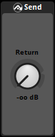
The send effect creates a duplicate of the signal and routes it to its partner effect the return effect. Sends exist in signal chains, and can be placed before or after specific effect modules in the chain in order to duplicate the signal before or after it is processed by those effects modules.
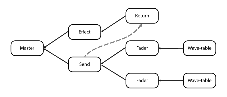
A DSP graph showing a send and return deviating the signal from its normal signal flow, sending the signal (visible as grey dashed arrow) from the send, and receiving it on the return.
The send effect is built on the FMOD Engine's send effect.
Performance: Low overhead.
- Target (Label)

- The target partner DSP.
- Level (Dial)

- Adjust the level of the send signal.
- Range: -oo to 10db. Default value: -oodB.
Automatable and Modulatable.
18.17 Sidechain

The sidechain effect creates a duplicate signal that may be used by an effect or modulator that can be sidechained, such as a compressor effect or a sidechain modulator.
Performance: Low overhead.
- Level meters (Level meters)

- These meters indicate the signal strength of each speaker channel of the duplicate sidechain signal. The number of meters corresponds to the number of channels in the signal's channel format, and their order is determined by the metering channel order setting in the audio tab of the preferences window. Within each meter, the filled colored bar represents the RMS value of the corresponding speaker channel's signal in dB, and the line above it represents the peak value of that speaker channel.
- Level (Dial)

- Adjusts the level of the duplicate sidechain signal.
- Range: -oo dB to 10 dB. Default value: 0 dB.
Automatable and Modulatable.
18.18 Spatializer

The spatializer effect is a multi channel, multi speaker signal distribution effect that combines 2D and 3D panning controls with built-in parameters to make the signal sound as if it came from a particular direction and distance.
Spatializer effects always output the speaker channel format specified for the current platform in the "build" tab of the preferences dialog. This means that if a spatializer effect's input signal is in a different speaker channel format, the effect up-mixes or down-mixes the signal at its position in the signal chain.
Under-the-hood, the spatializer effect uses the same code as the panner, and so can process the signal in the exact same ways.
The spatializer effect is built on the FMOD Engine's pan effect.
Performance: Low overhead.
- Distance Attenuation (Radio buttons and roll-off graph)
- This is the roll-off mode used to change the relationship between audio attenuation and distance. The available roll-off modes are:
-
- Linear Squared. Linear Squared roll-off keeps the volume unattenuated below the min distance, then attenuates to silence using a linear squared gradient to silence at the max distance. This gives it a faster roll-off near the min distance, and a slower roll-off nearer to the max distance than linear mode.
-
-
- Linear. Linear roll-off keeps the volume unattenuated below the min distance, then attenuates to silence using a linear gradient to silence at the max distance.
-
-
- Inverse. Inverse roll-off keeps the volume unattenuated below the min distance, then attenuates at a rate using min distance / distance as the gradient until it reaches max distance where it stops attenuating.
-
-
- Inverse Tapered. Inverse tapered is a combination of "inverse" roll-off and "linear squared" roll-off. From min distance onwards "inverse" is used, and then if the gain is lower with "linear squared", it will switch to that to ensure the gain hits silence at the max distance.
-
-
- Off. No distance-based attenuation is applied.
-
- Envelopment (Radio)
- This determines the extent of the event at any distance from the listener.
-
- Auto. Auto mode sets min extent to 0 degrees and sets sound size to twice the spatializer's min distance property, and is usually sufficient to prevent event instances from suddenly "flipping" from one side of the listener to the other when they pass the listener at close range.
-
- User. User mode allows you to specify the object spatializer's sound size and min extent manually using the "sound size" and "min extent" controls.
-
- Off. Off mode disables the "sound size" and "min extent" controls.
-
Default value: Auto.
- Sound Size (Dial)
- The sound size has an effect on the panner's extent, based on how 'large' the sound is. A very small sound is concentrated more into a point source (a small extent) and a large sound is spread around the speakers more to convey a sense of envelopment (a large extent).
- Range: 0 to 10000. Default value: 0.
Automatable and Modulatable. - Min Extent (Dial)
- The min extent has an effect on the panner's extent, by acting as a clamp against the sound size's effect on it. If a sound size becomes small which can reduce the distribution of pan to a point source, the min extent can set an angle to guarantee that the spatializer does not distribute the signal below this value.
- Range: 0 deg to 360 deg. Default value: 0 deg.
Automatable and Modulatable. - Distance Override (Drawer)
-
- Drawer containing the "override" and "min & max distance" controls.
- Override (Radio)
- This can be used to override the event's min and max distance property controls.
-
- On. On disables the event's min and max distance property controls and enables the "min & max distance" slider, allowing you to specify a different min & max distance for the effect.
-
- Off. Off mode disables the Min & Max slider and enables the event's min and max distance property controls.
-
Default value: Off.
- Min & Max Distance (Draggable slider)
- The min and max distance properties are used by spatializing effects in order to calculate attenuation falloff. Additionally, the value of the normalized distance property is calculated using the min and max distance property values. The min and max distance property controls are only interactive if "override" is set to "on".
- Range: 0 to 10000. Default range: [1,20].
Automatable and Modulatable. - 2D Pan Mix (Drawer)


- Drawer containing the "mix", "panner", "direction", "extent", "axis", and "width" controls.
- Mix (Dial)

- Allows you to blend between the manually defined "panner" settings and the automatic panning based on the playing event's position relative to the listener. At 0% the manually defined "panner" settings are ignored, and at 100% the automatic panning is ignored.
- Range: 0% to 100%. Default value: 0%.
Automatable and Modulatable. - Panner (Mouse-editable graphic)

- The panner in L/R mode.

- The panner in distributed mode.
- The surround panner lets you pan the signal between all available speakers by clicking and dragging the white dot at its center. This alters the effect's "direction" and "extent" properties.
- If the effect's input signal's channel format is stereo, the surround panner has two possible modes for converting the stereo signal to surround. In "Stereo In: Distributed" mode, the surround panner lets you pan the signal between all available speakers by clicking and dragging the white dot at its center, as above. In "Stereo In: L/R" mode, the white dot represents the left speaker and the red dot represents the right speaker. Moving the empty circle pans the sound (altering the "axis" property), and moving the red or white dots adjusts the stereo width (altering the "width" property). To switch between these two modes, right-click on the panner and select your choice of mode from the context menu.
- Direction (Number box)

- The direction in which the signal is panned. This control only appears if either:
-
- The input signal is not stereo.
-
- The input signal is stereo and the spatializer's panner is in "Stereo In: Distributed" mode.
-
Range: -180 deg to +180 deg. Default value: 0 deg.
Automatable and Modulatable. - Extent (Number box)

- The size of the arc over which sound is distributed in the output speaker circle. This control only appears if either:
-
- The input signal is not stereo.
-
- The input signal is stereo and the spatializer's panner is in "Stereo In: Distributed" mode.
-
Range: 0 deg to 360 deg. Default value: 360 deg.
Automatable and Modulatable. - Axis (Number box)

- The orientation of the arc over which sound is distributed in the output speaker circle. This control only appears if the input signal is stereo and the spatializer's panner is in "Stereo In: L / R" mode.
- Range: -180 deg to +180 deg. Default value: 0 deg.
Automatable and Modulatable. - Width (Number box)

- The width of the pan distribution or size of the arc over which sound is distributed in the output speaker circle. This control only appears if the input signal is stereo and the spatializer's panner is in "Stereo In: L / R" mode.
- Range: -180 deg to +180 deg. Default value: 60 deg.
Automatable and Modulatable. - LFE (Slider)

- The LFE slider controls the volume being sent to the LFE (subwoofer).
Automatable and Modulatable. - Level meters (Level meters)

- These meters indicate the signal strength of each speaker channel of the signal output by the effect. Spatializer effects always output the channel format specified for the platform in the "build" tab of the preferences dialog.
- The number of meters corresponds to the number of channels in the signal's channel format, and their order is determined by the metering channel order setting in the audio tab of the preferences window. Within each meter, the filled colored bar represents the RMS value of the corresponding speaker channel's signal in dB, and the line above it represents the peak value of that speaker channel.
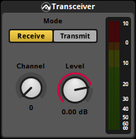
18.19 Transceiver
Like the Send and Return effects, the transceiver effect allows signals to be routed from one place in the mix to another.
There are 32 separate channels to which a transceiver can transmit an audio signal to or receive audio from.
A transceiver can be set to:
- Receive mode, where signal from the selected channel is received at a variable gain, similar to a return.
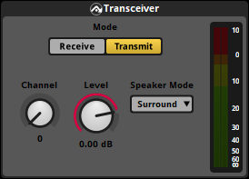
- Transmit mode, where it transmits a duplicate of the signal at its position in the mix, with a variable gain, to the selected channel, similar to a send.
This allows transceivers to be used in a variety of different ways. A common application is for one transmitting transceiver's signal to be received by an unlimited number of receiving transceivers, making that signal audible in multiple different parts of the mix. In a 3D world, this could allow one expensive emitter (i.e.: a stream) to be broadcast to different 3D locations around the world simultaneously, at low CPU cost.

Sounds being transmitted by 2 transceivers in transmit mode, one sound transmitting to channel 0, and the other to channel 1. There is then a 3D scene with 5 transceivers tuned to either channel 0 or 1, which lets them broadcast the transmitted signal from different locations simultaneously.
Characteristics of the transceiver effect:
- Upon receiving the signal on the receive side, it is buffered and therefore will incur one mix block of latency.
- Multiple transmitters sending to the same channel are mixed together.
The Transceiver effect is built on the FMOD Engine's transceiver effect.
Performance: Low overhead.
To reduce memory overhead, aim to use the same transmit speaker mode for a channel.
- Mode (Radio buttons)
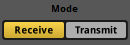
- Current transceiver mode. This can be either receive or transmit.
- Channel (Dial)

- Dial to control the receiver channel. Can be set to receive or transmit.
- Range: 0 to 31. Default value: 0.
- Level (Dial)

- Adjust the level of the signal to be sent in transmit mode, or received in receive mode.
- Range: -oo to 10dB. Default value: 0 dB.
Automatable and Modulatable. - Speaker Mode (Dropdown menu)

- Exposed in transmit mode, controls the speaker layout to be transmitted. This can be auto, mono, stereo or surround. Speaker mode is the speaker mode chosen in the Platform Settings.
- Level Meters (Level meters)
- These meters indicate the signal strength of each speaker channel either being transmitted or received. The meter layout is determined by the channel format of the audio track. Within each meter, the filled colored bar represents the RMS value of the corresponding speaker channel's signal in dB, and the line above it represents the peak value of that speaker channel.